Design Problem 1
Click here for Design Problem 2
The text below outlines the initial design challenge presented to my team during the introductory engineering course. Our objective was to create two remotely controlled rescue robots capable of efficiently deploying a bridge to facilitate the rescue of stranded individuals in the shortest time possible. To achieve this goal, we engaged in a comprehensive brainstorming process to generate a range of innovative solutions.
The Concepts


We generated several concepts through brainstorming and tools like AI. After gathering enough ideas, we ranked them using screening matrices to identify the best options based on our criteria. On the left, you can see the matrix for the Rescue Bot, and on the right is the matrix for the Bridge Bot.


From this, we chose the Arm Bot for the Rescue Bot and the Rotating Bridge for the Bridge Bot(The Mega Bridge was deemed illegal).
Prototyping

The Arm Bot
Following several iterations of trial and error, the rescue robotics team successfully developed a prototype utilizing a Raspberry Pi 2, a compact breadboard, an MG995 servo, four brushless electric motors, and various components produced through 3D printing and laser cutting techniques. Regrettably, this prototype did not withstand the testing phase, as it struggled to consistently meet the primary objective of efficiently retrieving three stranded individuals within a limited timeframe.
Semi-Final Version
After some refinement, we landed on this final design. Despite its improved base and organization, this had to be scrapped due to its ineffectiveness.

The Bridge Bot
The image to the right showcases the initial prototype of the bridge robot, prominently featuring the rotating bridge as illustrated in the design concepts. This prototype is equipped with two MG995 servos, two electric motors, and a Raspberry Pi 2, complemented by a Kitronik motor kit. I was not part of the team that developed this prototype, so I am unable to provide specific insights into the challenges encountered during the development process.
The Final Prototype
After some refinement, the Bridge bot was completed with minor upgrades, primarily in the positions of the wheels and servos. It’s also important to mention the bridge itself.

The Bridge
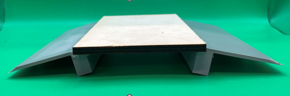
The Bridge was a relatively simple design. Not many reiterations were required as it was easier to change the design of the bridge bot to be compatible.

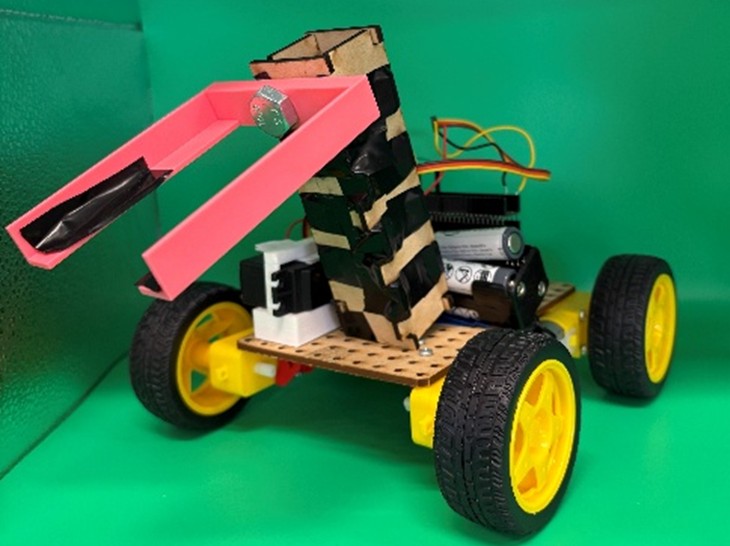
The Final Final Bridge Bot
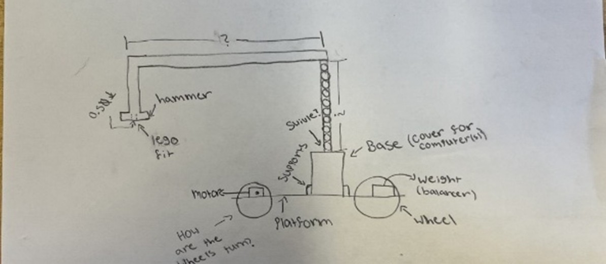
Following the failure of our previous design, we returned to the drawing board to develop a new solution. We opted for a sweeping arm mechanism, which significantly simplifies the process of lifting the individuals. These individuals will be directed into the box depicted, which features white skirts. The more complex aspect of the design involved creating an arm that could seamlessly attach to the servo. As illustrated, we utilized screws and electrical tape to securely fasten the two components together.
Testing
Unfortunately, we did not have a large amount of time for testing. We completed approximately three rounds of testing. Below is a table of the points awarded and the points allocated for time.


Competition
Following the completion of our testing phase, we felt optimistic about our potential performance in the competition. Each design problem was allotted two test runs. The initial run of Design Problem 1 (DP1) demonstrated some success, although we encountered timing issues due to a connectivity problem midway through the run. The second attempt showed improvement, yet the timing remained suboptimal at approximately 1:30. I have included a video showcasing a significant portion of this run. Fortunately, the judges opted to combine the highest scores from each team for the final rankings. Ultimately, we achieved a fifth-place finish and excelled in the presentation category, for which we were honored with an award.
Below is a PDF version of the Presentation
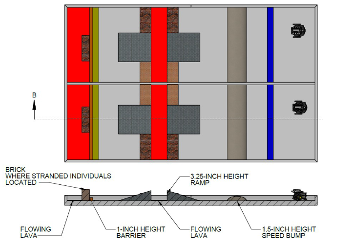
Design Problem 2

The layout presented above illustrates the specifications for the second design challenge. In this case, our objective was to develop a fully autonomous rescue robot that relied solely on the programming of the microcontroller and the employed sensors. Teams had the option to choose between infrared (IR) distance sensors and bump sensors for navigation; my team opted to utilize only distance sensors.
Given the narrow gaps between the walls in the course, we reduced the dimensions of our robot to approximately 3 inches in width and 5 inches in length. This necessitated the fabrication of most of the robot’s components from scratch, a departure from our previous projects. While constructing the base and support structure was relatively straightforward using SolidWorks and laser cutting technology, the design of the sensor holder presented more complex challenges.
IR Distance Holder

Above is the drawing file of the IR Holder. This was the central piece to the project. By the early stages of prototyping, we had created this:

Prototyping
Once the bot was fully assembled, we encountered the next significant challenge: coding. My team decided to prioritize the completion of the coding phase prior to finalizing the prototype, as this approach allowed for a higher quality outcome by accommodating necessary adjustments. The coding process itself was relatively manageable, though we faced challenges in addressing errors arising from the inexpensive IR sensors. By the conclusion of our testing phase, we achieved a runtime of approximately 30 seconds, with the shortest recorded time being 20 seconds. It was at this stage that we integrated the final component, which securely held the LEGO figure. I will provide a final PDF that includes the code for your reference.

In the initial design, a bucket was incorporated to securely hold the LEGO figure, which may have been somewhat excessive. As with our first design prototype, we conducted two trial runs to maximize our score potential. The performance of the first run was not as optimal as anticipated, primarily due to a unique quirk in the code that occasionally caused the bot to execute an unnecessary complete turn. This issue resulted in a run time exceeding two minutes, which was less than ideal. Fortunately, the second run was executed nearly flawlessly, completing the course in approximately 40 seconds. Regrettably, I do not have video footage of either run.
Final Thoughts
This project was both enjoyable and personally enriching. I appreciated the opportunity to explore topics such as SolidWorks and Python, and to apply my knowledge directly in a project setting. The challenges we faced fostered a wide range of innovative solutions, which was exciting to observe, particularly in collaboration with other teams. I am thankful for the chance to participate in this event; the experience gained with my team was invaluable. We performed well, ultimately placing fifth overall. Unfortunately, this positioning meant we did not receive any of the bear trophies awarded. I look forward to leveraging what I learned and hope to engage in similar events as I continue my journey at WNEU.
Appendix
Below is the final design history file, which includes images of bots, testing results, code, and drawings for major parts created.